Mechanical constraints
Mechanical constraints behave as conceptual mechanical connections such as hinges, springs, and motors.
The physics engine includes the following Constraints that behave as conceptual mechanical connections, including hinges, springs, ropes, and more. In addition, various mover constraints are available to exert directional or rotational force upon assemblies.
BallSocketConstraint forces its two attachments into the same position and allows them to freely rotate about all three axes, with optional limits to restrict both tilt and twistHingeConstraint allows its two attachments to rotate about one axis, with optional assigned power for motor or servo behaviorPrismaticConstraint allows two attachments to slide along one axis but not rotate, with optional assigned power for mechanisms like sliding doors and elevator platformsCylindricalConstraint allows its attachments to slide along one axis and rotate about another axis, with optional assigned angular and/or linear powerSpringConstraint applies a force on its attachments based on spring and damper behavior, with an optional minimum/maximum lengthTorsionSpringConstraint applies torque based on a relative angle and relative angular velocity, in an attempt to bring two axes from two parts togetherUniversalConstraint ensures two axes on two assemblies remain perpendicular, useful for applications such as vehicle power transmission to rear drive shafts, robotics, and moreRopeConstraint prevents two attachments from separating further than a defined length, with optional behavior as an extending or contracting winchRodConstraint keeps two attachments separated by a defined length, with optional limits on rotational tiltPlaneConstraint moves two attachments into a position/orientation along a plane, and both attachments remain free to translate and rotate unless otherwise constrainedWeldConstraint connects two BaseParts and ensures they stay in the same relative position and orientation to each other, even if they are not touchingRigidConstraint connects two Attachments or Bones and ensures they stay in the same relative position/orientation to each other, even if they are not touchingNoCollisionConstraint prevents collisions between two specific parts, but those parts may still register collisions with the rest of the worldConstraint visualization#
To accurately visualize constraints in Studio, you can toggle the following from the View menu or through the respective shortcut:
- Show Welds (AltW or ⌥W) — Show
WeldConstraintsseparately from the visualization of other constraints. - Show Constraint Details (AltD or ⌥D) — Show complete visual details of non-weld constraints.
In addition to the above visualization, you can view colored outlines around mechanisms (groups of parts that share simulation step and network ownership) by toggling on Mechanisms from the Visualization Options widget in the upper‑right corner of the 3D viewport.
Create constraints#
All mechanical constraints must connect one or two Attachments or Bones, except for WeldConstraint and NoCollisionConstraint. When connected to Bones, the constraint will use their animated position and orientation.
To create a mechanical constraint, you can either insert one from the Constraint picker/button or through the Explorer window.
Constraint Picker
In Studio's Model tab toolbar, click‑hold over the small corner arrow on a constraint button to open its picker menu, then select the desired constraint.

In the 3D viewport, hover over any
PartorMeshPartand click to add a newAttachmentto the part at the visualized point. Alternatively, hover over and click an existingAttachmentorBoneto use it for the constraint.Most mechanical constraints require a secondary attachment in their functionality, so the tool will typically prompt you to repeat the previous step on another
Part,MeshPart,Attachment, orBone.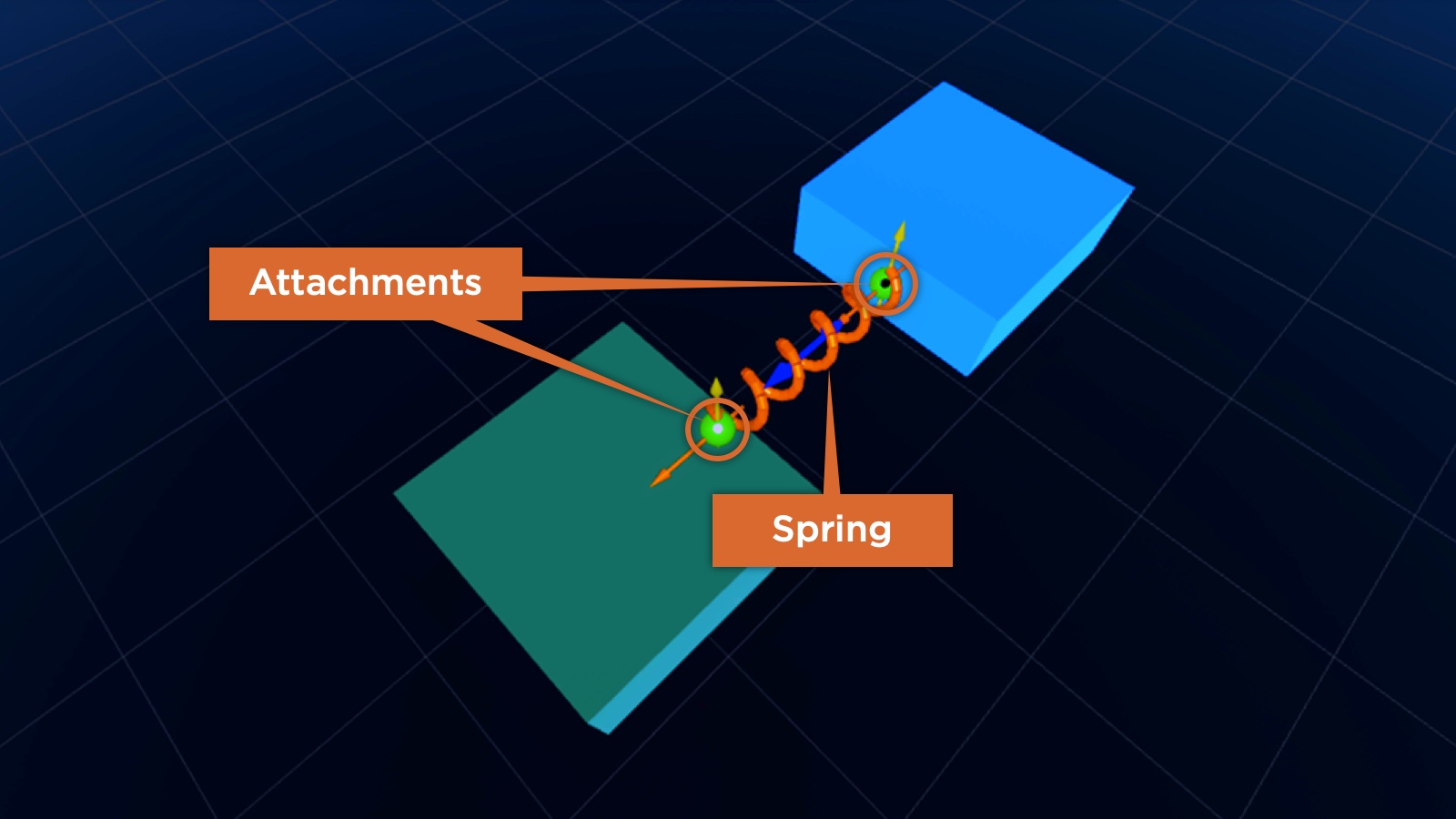
Completed SpringConstraint connecting two attachments
Explorer
Note that WeldConstraint and NoCollisionConstraint do not utilize Attachments or Bones, so their linking properties in the following steps are Part0/Part1, not Attachment0/Attachment1. Similarly, you'll need to select a Part or MeshPart to complete the link, not an Attachment or Bone.
In the Explorer hierarchy, hover over the intended parent, click the ⊕ button, and insert the desired constraint from the dropdown menu, such as a SpringConstraint.
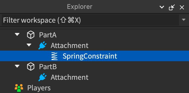
With the new constraint selected, locate its currently empty Attachment0 property in the Properties window.
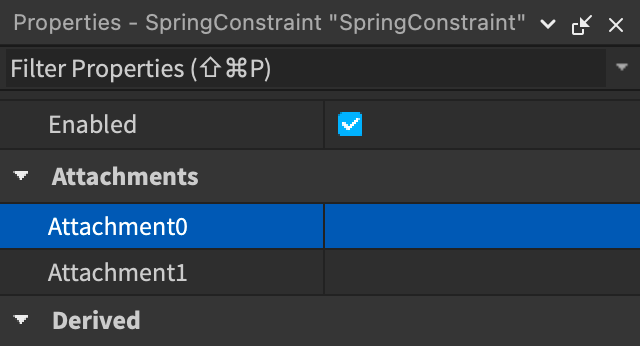
Link the Attachment0 property to an
AttachmentorBonein two consecutive steps:In the Properties window, click in the Attachment0 row to reveal the selection cursor.
In the Explorer hierarchy, click on the target
AttachmentorBone.
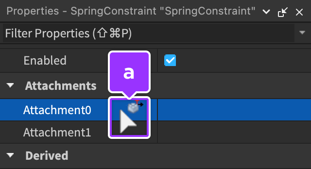
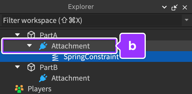
- Most mechanical constraints require a secondary
AttachmentorBonein their functionality. If necessary, repeat the previous step on the Attachment1 property in the Properties window.
Physical simulation#
To simulate physics while moving or rotating parts, you can switch from Geometric mode to Physical mode in Studio's toolbar, effectively forcing parts to obey physical limitations. For example, if two parts are attached by a RopeConstraint and you drag one part around the scene, the other part will follow as the rope becomes taut.
